
Karri, if you tune for 1 hour per session, and you tune 1000 times, you're tune is so polished that the engine will be singing sweetly after about 25 hours, ie, you're wasting time, or, more realistically, you'll never wear out the plug in this application. Spudmn is on the money IMO.
Fred.
Puma board for FreeEMS
Re: Puma board for FreeEMS
DIYEFI.org - where Open Source means Open Source, and Free means Freedom
FreeEMS.org - the open source engine management system
FreeEMS dev diary and its comments thread and my turbo truck!
n00bs, do NOT PM or email tech questions! Use the forum!
The ever growing list of FreeEMS success stories!
FreeEMS.org - the open source engine management system
FreeEMS dev diary and its comments thread and my turbo truck!
n00bs, do NOT PM or email tech questions! Use the forum!
The ever growing list of FreeEMS success stories!
Re: Puma board for FreeEMS
It's not about whether it's to be unplugged 10k times, it is an indicator on overall toughness as well. My experience with micros have been better than minis. I've got mini plugs that fall out on their own and others that need a prybar to get loose. I have connectors with crumbled housing that had to be bent back into shape with a screwdriver. Anyone had bad experiences with micro, now is the perfect time to share tales!
-
GartnerProspect
- LQFP112 - Up with the play
- Posts: 160
- Joined: Tue Apr 08, 2008 9:14 pm
Re: Puma board for FreeEMS
Citation Necessary.Spudmn wrote:What I am most concerned about is lateral force.KW1252 wrote:Micro USB specification requires minimum of 10 000 mating cycles for the connectors, which is considerably more than Mini (which is around 1000 I believe).
Let's think about how this is going to be used. We are going to bolt the ECU to the car and have the USB cable running up to our laptop. Sooner or later we are going to trip, kick or pull on that cable.
The lateral force is going to break a micro USB. This is less of a problem with cell phones because when you pull on the cable the light cell phone moves instead of breaking the cable.
I'm not saying that you can't break the Mini plug but it is stronger than the Micro.
Anecdotally I have broken more Mini's vs. Micro. Micro is the newer design and I suspect the mounting is better thought out as most of my Mini failures were due to pulling the pads off the boards. Foolishly they were entirely SMD. If the Micro connector employes a through hole reinforcement I vote for the Micro. Otherwise it's a wash because the pads are gonna be the weakest link. Other than that, it really comes down to part availability and life-cycle and cost. I don't thing either one is truly superior outside of those constraints.
Re: Puma board for FreeEMS
I was thinking this too, as I pulled a few pads off my puma before I got good at modifying it :-) You're dead right.GartnerProspect wrote:Otherwise it's a wash because the pads are gonna be the weakest link.
DIYEFI.org - where Open Source means Open Source, and Free means Freedom
FreeEMS.org - the open source engine management system
FreeEMS dev diary and its comments thread and my turbo truck!
n00bs, do NOT PM or email tech questions! Use the forum!
The ever growing list of FreeEMS success stories!
FreeEMS.org - the open source engine management system
FreeEMS dev diary and its comments thread and my turbo truck!
n00bs, do NOT PM or email tech questions! Use the forum!
The ever growing list of FreeEMS success stories!
-
GartnerProspect
- LQFP112 - Up with the play
- Posts: 160
- Joined: Tue Apr 08, 2008 9:14 pm
Re: Puma board for FreeEMS
That said, perhaps a USB pin header and a panel mount USB port would be a nice build-time option. Though in any permanent install, I would certainly use a USB extension mounted somewhere convenient.Fred wrote:I was thinking this too, as I pulled a few pads off my puma before I got good at modifying itGartnerProspect wrote:Otherwise it's a wash because the pads are gonna be the weakest link.You're dead right.
Re: Puma board for FreeEMS
Mate, where the hell have you been for the last 6 months??? :-p Another fine idea! :-)GartnerProspect wrote:That said, perhaps a USB pin header and a panel mount USB port would be a nice build-time option. Though in any permanent install, I would certainly use a USB extension mounted somewhere convenient.
DIYEFI.org - where Open Source means Open Source, and Free means Freedom
FreeEMS.org - the open source engine management system
FreeEMS dev diary and its comments thread and my turbo truck!
n00bs, do NOT PM or email tech questions! Use the forum!
The ever growing list of FreeEMS success stories!
FreeEMS.org - the open source engine management system
FreeEMS dev diary and its comments thread and my turbo truck!
n00bs, do NOT PM or email tech questions! Use the forum!
The ever growing list of FreeEMS success stories!
Re: Puma board for FreeEMS
+1!GartnerProspect wrote:That said, perhaps a USB pin header and a panel mount USB port would be a nice build-time option. Though in any permanent install, I would certainly use a USB extension mounted somewhere convenient.Fred wrote:I was thinking this too, as I pulled a few pads off my puma before I got good at modifying itGartnerProspect wrote:Otherwise it's a wash because the pads are gonna be the weakest link.
I wouldn't drill holes to the cinch box either
Re: Puma board for FreeEMS
I vote, we include the mini/micro and header pins.
I don't like the header pin(s) idea, as they are another place for a signal to go wrong, but I can see the desire if you have space constraints that prevent you from putting a strain relief on the USB cord.
I'm seeing if I can smash together min/micro/header footprint module now.
I don't like the header pin(s) idea, as they are another place for a signal to go wrong, but I can see the desire if you have space constraints that prevent you from putting a strain relief on the USB cord.
I'm seeing if I can smash together min/micro/header footprint module now.
-
GartnerProspect
- LQFP112 - Up with the play
- Posts: 160
- Joined: Tue Apr 08, 2008 9:14 pm
Re: Puma board for FreeEMS
That was my first instinct as well. Then I got to thinking about computer motherboards with a number of USB ports on header pins that I've used successfully for years and years. Granted, that's a product with a fair bit more R&D invested and admittedly lower/more predictable noise sources... Seems for as much as I lean towards throwing the kitchen sink and a small kitten at the board, there is a definite concern about small changes/additions creating larger problems that need to be carefully balanced. This is one of themjharvey wrote:I vote, we include the mini/micro and header pins.
I don't like the header pin(s) idea, as they are another place for a signal to go wrong, but I can see the desire if you have space constraints that prevent you from putting a strain relief on the USB cord.
I'm seeing if I can smash together min/micro/header footprint module now.
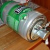
A quick search brought me to this little gem:

Would provide for a very clean install, transfer cable stress away from the PCB, and add convenience. No need for header pins and everybody is happy.
Too many projects, too many women!Fred wrote: Mate, where the hell have you been for the last 6 months??? :-p
Re: Puma board for FreeEMS
I just created a footprint for the combo u-mini-header, and pushed to github.
About all this stress relief on a data connector, shouldn't we jump the wireless gap? I'd still like to see a chip we can put on puma, that emulates 232 to the MCU, and a software driver on a PC that emulates a 232 connection, but have the actual medium be 802.11. Such that we simply tell the existing soft to use say com9, which a driver then translates into 802.11, and sends out on your laptops wireless. Then the chip receives the 802.11 signals, and relays 232 to the MCU. I'm sure such a device has to exist, but I haven't found it yet.
About all this stress relief on a data connector, shouldn't we jump the wireless gap? I'd still like to see a chip we can put on puma, that emulates 232 to the MCU, and a software driver on a PC that emulates a 232 connection, but have the actual medium be 802.11. Such that we simply tell the existing soft to use say com9, which a driver then translates into 802.11, and sends out on your laptops wireless. Then the chip receives the 802.11 signals, and relays 232 to the MCU. I'm sure such a device has to exist, but I haven't found it yet.