Fred wrote:These other systems work on the basis that the valves are linear don't they?
I believe so.
Fred wrote:I'm not sure what you mean by these limits etc though.
I'll try and explain better below.
thebigmacd wrote:The issue with Megasquirt is the I term wasn't actually an I term, it was a P term. I believe they are fixing this for MS3.
I don't know about MegaSquirt, but maybe VEMS did the same thing? I'm doubtful though. See below.
thebigmacd wrote:As far as non-linearities, the loop for sure should be a hybrid of feed-forward and feed-back control. Good control should be approximated with an open-loop curve and adders for known additional loads. Then a simple PI controller can be used to fine tune it within a 100 rpm (or so) range.
I think I'll explain what I've seen here and it will touch on all the issues raised above.
The PID idle control for VEMS took me a long time to figure out, but here's the deal. First you tune the PWM table which is about 10 spots of temp versus PWM value (direct DC % to idle valve). (This is what thebigmacd is talking about above when he says good control should be approximated with an open-loop curve.) Something like this:
[-60] --> [90]
[-40] --> [88]
[-20] --> [86]
[0.0] --> [84]
[15] --> [82]
[30] --> [80]
[45] --> [78]
[60] --> [76]
[75] --> [50]
The idea is that you get this as close as possible to the behavior you'd like. This is important because this is the base value the PID controller in VEMS starts with once idle is enacted. So if you close the throttle at 45 degrees the idle % DC value starts at 78 and then PID takes over adjusting that as it sees fit. If you close the throttle at high rpms, idle turns on and sees that rpms are way, way off so PID will drop the DC % value to a very low number which seems counter intuitive, because to "catch" the falling rpm you'd want something even higher than the 78 you started with. But I digress....
I had a year under my belt dealing with this idle control, and just finally realized that the idle solenoid was not linear. After sleeping on it I came up with a plan. I'd set all the PWM values to something high:
[-60] --> [85]
[-40] --> [85]
[-20] --> [85]
[0.0] --> [85]
[15] --> [85]
[30] --> [85]
[45] --> [85]
[60] --> [85]
[75] --> [85]
And I wouldn't give any authority to "P" which changes things much too fast and at the worst times for use in idle if you ask me.
I decided to start with "I" and was quickly rewarded with a great "catch" of idle because even while fully warmed up idle % DC would start off at 85 (which was good for about 1,400 rpm) and then "I" slowly worked it's magic bringing down the idle % DC value with a corresponding slow drop in idle until about 1,000 rpms and maybe a % DC value of 60.
Uhhh... wait a minute. Why did it stop going down? My target was 850 rpm.
From everything I've read about PID control it should adjust until the target (850 rpm) is reached.
Here's the window. Ignore the current values of everything actually. Imagine P = 0, I= 5, D = 0 and "integral decrease/increase limit" is set at 255 (highest).
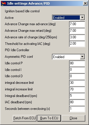
This allows for a deviation of about 25 % DC from the initial PWM value designated in the table. Lower the "integral decrease/increase limit" values and things get worse, only allowing for less than 25 % DC change depending on the value. You get the idea.
Yes, you can make "I" higher than 5 and it will bring things further than 25 % DC deviation, but it will act much too fast to allow the good "catch" of falling idle, etc. etc. etc.
Does that make it any clearer?
Once understood, Nissan's idle control valve being non linear makes a lot of sense. You can use the lower 75% as a fine tune mechanism to keep warm idle solidly in check. This however doesn't give enough air for cold/fast idle so the top 25% is used for that where only coarse tuning is really necessary. Additionally, as the % DC falls across the threshold from lots of air to a little bit of air you get a crisp, distinguishable drop in idle quickly (idle "catches" then drops to 850 rpm quickly, with purpose) with the tiniest drop in actual % DC value, and this tiny drop is all that's needed, and all that will be provided by a small "I" value. It would work so perfectly if VEMS would just allow the PID control to keep on truckin' instead of limiting things artificially (they may have been worried about the run-a-way "I" value which I've read needs preventing, but I digress again).
In conclusion, it just seems that the writers of the PID control never anticipated an "I" control, and only ever considered a "P" control, a "PI" control, or a "PID" control. A non-linear idle control valve seems to take advantage of a strictly "I" control. My advice is to keep this in mind when writing and testing the PID code. Even a value of 1 for "I" should get the system under control (if slowly).