Looks like I'll jump on this one next. Fred posted about it here and it looks fairly easy.
http://www.diyefi.org/forum/posting.php ... &f=9&t=333
It requires a custom symbol, so I stared on that. It can come in a 6 pin or 8 pin device. Which should I go with?
MAP sensor circuit

Re: MAP sensor circuit
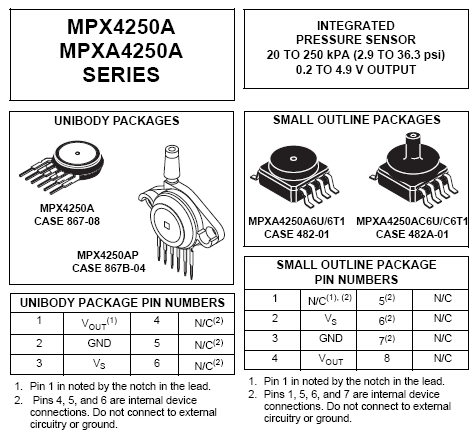
I think 8 pin are most common, I haven't seen/heard of the 6 pin variant at all, can you link?
DIYEFI.org - where Open Source means Open Source, and Free means Freedom
FreeEMS.org - the open source engine management system
FreeEMS dev diary and its comments thread and my turbo truck!
n00bs, do NOT PM or email tech questions! Use the forum!
The ever growing list of FreeEMS success stories!
FreeEMS.org - the open source engine management system
FreeEMS dev diary and its comments thread and my turbo truck!
n00bs, do NOT PM or email tech questions! Use the forum!
The ever growing list of FreeEMS success stories!
Re: MAP sensor circuit
Um the one on the left has 6 pins. Granted it's thru hole, but you can SMT it if you wanted to.
Any how, 8 pin 482A-01 case. Got it.
I'm out sick from work again, so I might make more progress on this again.
Any how, 8 pin 482A-01 case. Got it.
I'm out sick from work again, so I might make more progress on this again.
Re: MAP sensor circuit
Sorry, I see what you mean.
I meant one SMD style one for atmospheric correction onboard. You could leave room for a main map sensor in either package on there too, but people may like to leave that external to the ecu entirely. I personally would run a hose for my atmospheric readings too so I could choose a pressure neutral area on the vehicle to sample from.
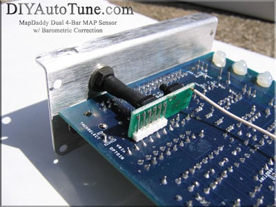
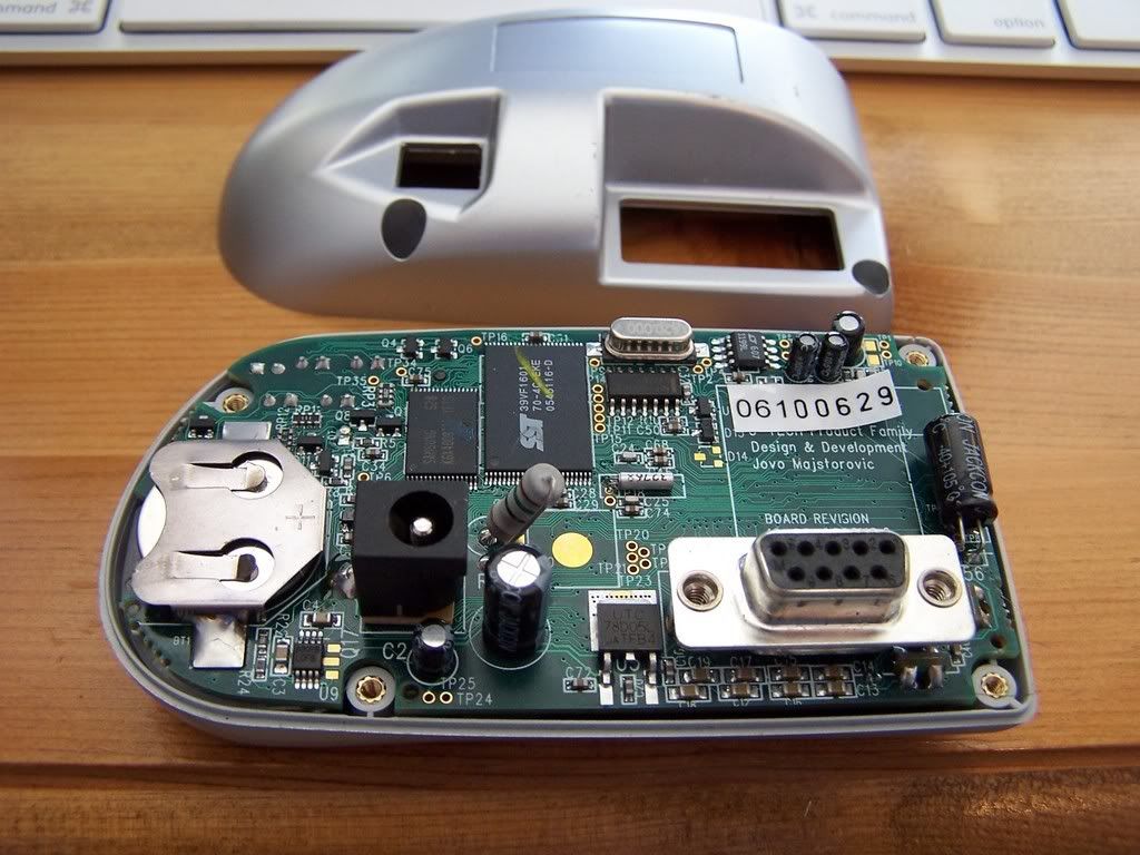
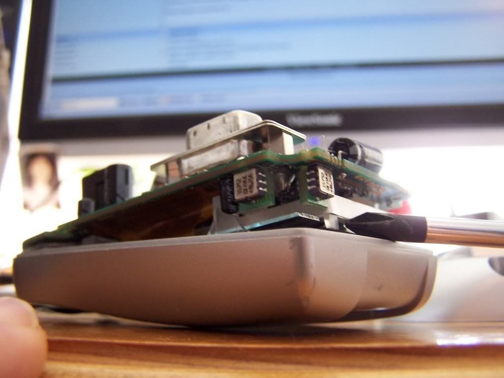
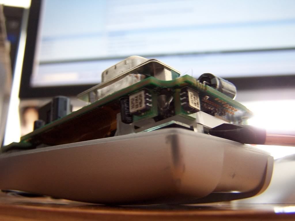
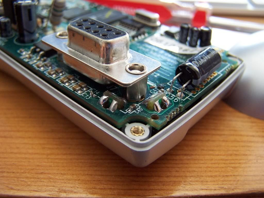
An alternative would be to design a little card that itself surface mounts to the main PCB with two smd map sensors on it to make them point horizontally.
Something like this :
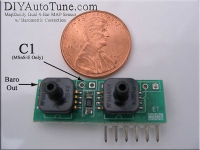
Or this :

Only, perhaps mounted like this :
http://i238.photobucket.com/albums/ff26 ... 0_8613.jpg
http://i238.photobucket.com/albums/ff26 ... 0_8612.jpg
http://i238.photobucket.com/albums/ff26 ... 0_8611.jpg
http://i238.photobucket.com/albums/ff26 ... 0_8610.jpg
http://i238.photobucket.com/albums/ff26 ... 0_8609.jpg
or something
Fred.
I meant one SMD style one for atmospheric correction onboard. You could leave room for a main map sensor in either package on there too, but people may like to leave that external to the ecu entirely. I personally would run a hose for my atmospheric readings too so I could choose a pressure neutral area on the vehicle to sample from.
An alternative would be to design a little card that itself surface mounts to the main PCB with two smd map sensors on it to make them point horizontally.
Something like this :
Or this :
Only, perhaps mounted like this :
http://i238.photobucket.com/albums/ff26 ... 0_8613.jpg
http://i238.photobucket.com/albums/ff26 ... 0_8612.jpg
http://i238.photobucket.com/albums/ff26 ... 0_8611.jpg
http://i238.photobucket.com/albums/ff26 ... 0_8610.jpg
http://i238.photobucket.com/albums/ff26 ... 0_8609.jpg
or something
Fred.
DIYEFI.org - where Open Source means Open Source, and Free means Freedom
FreeEMS.org - the open source engine management system
FreeEMS dev diary and its comments thread and my turbo truck!
n00bs, do NOT PM or email tech questions! Use the forum!
The ever growing list of FreeEMS success stories!
FreeEMS.org - the open source engine management system
FreeEMS dev diary and its comments thread and my turbo truck!
n00bs, do NOT PM or email tech questions! Use the forum!
The ever growing list of FreeEMS success stories!
Re: MAP sensor circuit
Got it, so 2 sensors, one for MAP, one for ambient. Is that going to be 2 A/D's? Or will there be some way of switching between the two. I drew it up as 2 A/D's.
Re: MAP sensor circuit
Yeah, two of them, which physical format is really totally flexible, I tend to like the compact ones, especially for ambient measurement, but probably for both at the end of the day. The lack of screw mounting = more accurate readings too.
Here is the current ADC pin assignment, still subject to change, but not much. Do check before starting on the board layout and I'll review what I've done with the pins and make any final changes then.
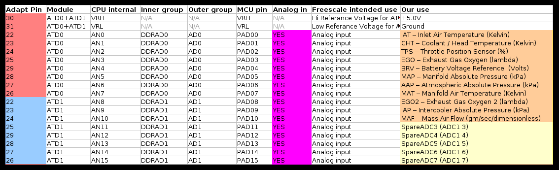
The basic idea is that each pin is hard assigned to a common function and if not being used for that can still be accessed via a programmable mechanism for any other sensor logging duties required.
We still have a few to go, but at some stage it might become feature X XOR Y for some ADC pins, or perhaps less common features will get a programmable pin like the general logging will to keep it flexible.
Fred.
Here is the current ADC pin assignment, still subject to change, but not much. Do check before starting on the board layout and I'll review what I've done with the pins and make any final changes then.
The basic idea is that each pin is hard assigned to a common function and if not being used for that can still be accessed via a programmable mechanism for any other sensor logging duties required.
We still have a few to go, but at some stage it might become feature X XOR Y for some ADC pins, or perhaps less common features will get a programmable pin like the general logging will to keep it flexible.
Fred.
DIYEFI.org - where Open Source means Open Source, and Free means Freedom
FreeEMS.org - the open source engine management system
FreeEMS dev diary and its comments thread and my turbo truck!
n00bs, do NOT PM or email tech questions! Use the forum!
The ever growing list of FreeEMS success stories!
FreeEMS.org - the open source engine management system
FreeEMS dev diary and its comments thread and my turbo truck!
n00bs, do NOT PM or email tech questions! Use the forum!
The ever growing list of FreeEMS success stories!
-
shameem
- LQFP112 - Up with the play
- Posts: 135
- Joined: Thu May 01, 2008 6:30 pm
- Location: Ann Arbor, MI
- Contact:
Re: MAP sensor circuit
Just curious.....
Why integrate the sensor with the board? and why MPX4250?
There are many stock sensors - especially bosh sensors used by chevy - why not use those?
I have come across about 3 instances where moisture condensed into MPX4250 sensors and altered readings.....
Why integrate the sensor with the board? and why MPX4250?
There are many stock sensors - especially bosh sensors used by chevy - why not use those?
I have come across about 3 instances where moisture condensed into MPX4250 sensors and altered readings.....
Re: MAP sensor circuit
Post the details! Provided they are linear, accurate and 5V it doesn't matter to me :-) Any can be supported in software. How hard to get are the bosch ones though? If you provide a part number I'll tell you if I can get them here and NZ, if not, the freescale might be the best choice just for availability.
DIYEFI.org - where Open Source means Open Source, and Free means Freedom
FreeEMS.org - the open source engine management system
FreeEMS dev diary and its comments thread and my turbo truck!
n00bs, do NOT PM or email tech questions! Use the forum!
The ever growing list of FreeEMS success stories!
FreeEMS.org - the open source engine management system
FreeEMS dev diary and its comments thread and my turbo truck!
n00bs, do NOT PM or email tech questions! Use the forum!
The ever growing list of FreeEMS success stories!

Re: MAP sensor circuit
VEMS's argument for on board MAP sensor was keeping electrical signal integrity. Something about it being the most important sensor, the need for accuracy being important. *shrug* I doubt it matters that much.
-
GrowlingandBiffo
- QFP80 - Contributor
- Posts: 56
- Joined: Sat Apr 26, 2008 7:42 am
Re: MAP sensor circuit
At the volumes discussed, availability is paramount.Fred wrote:Post the details! Provided they are linear, accurate and 5V it doesn't matter to meAny can be supported in software. How hard to get are the bosch ones though? If you provide a part number I'll tell you if I can get them here and NZ, if not, the freescale might be the best choice just for availability.
If it is not in stock at Digikey or Farnells you will have a problem.