Delta wrote:Only a fraction??
Yeah, only a fraction, how many cars that run standalones percentage wise do you think make more than 100hp per cylinder? That is easily supported by high Z injectors.
Most people who go after market ecu are installing one because the standard ecu no longer allows you to do what you want. Stock ecu's are generally deisgned for high Z injectors and a limited set of sensors.
And all the IO is used up and the ignition style is fixed and and and. I'd typically change to add boost and use non dizzy ignition. Or, even to ditch carbs!
Flash tuning (which is now very very common For Common Popular Platforms) allows you to modify within the limits of the ecu hardware/sensors....so generally the reason for changing is to support different sensors (perhaps for boost/massive NA mods) and different injector types.
Typically in the low budget DIY arena people use larger injectors off of other OEM applications. As you said, most are high Z. I don't want to ask, but probably Jean could shed some light on estimated percentages of MS users that need it.
If you limit yourself to saturation onboard then you are basically not offering a solution that keeps up with 99% of aftermarket gear. While I understand this is an open source effort and hence does not HAVE to be up to the standard of a commercial product - removing a key feature to an external board or leaving it out entirely sounds very MSish.
Key to who? You, Abe, and others, sure, but not to all potential users. Including it has its drawbacks. They can't be ignored, and if included they need to be handled very carefully. Even if we decide no low Z on board we aren't saying no low Z, we are just saying no low Z on board. Experience shows us that this does not deter many users. After all installing a second box with cylCount x2 +2 connections or so isn't exactly a big ask. Heaps of people use horrible resistor boxs with similar extra effort required.
Later on we can start adding things like my injector driver, onboard IGBT ignition, boost control, closed loop idle etc etc. But I think the second revision definitely SHOULD contain all possible features inside one case - even if they are plug in boards internally.
Having said all that, I'm all for it IF we can do it in a NICE way overall. Perhaps put your circuit on there and just suggest a good case IF using low Z. That simplifies it and supports it. BUT, we need to check out the RF side of it in detail IRL before committing to that. Putting a massive noise source in the case like that MUST be done with great care.
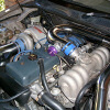
BTW - If I'm testing anything it will be going on the car in my avatar - currently it runs an EMS8860 and I have low Z injectors - Siemens Deka 72lb/h to be exact, so I'll need peak and hold as they are 2.8ohms.
Speaking of the car in your avatar, care to put up a thread about it in user rides? Looks cool :-)
Also, looks like an old school 6 pot, did it have an ECU at all stock? I think not = one of the biggest reasons to go aftermarket. IE, old engine or blank slate setup.
Thread discussing FreeEMS and how it will measure up to other stuff once functional and fairly complete (to keep this one on topic) :
http://www.diyefi.org/forum/viewtopic.php?f=41&t=385
Fred.