
Admin.For example, in an automobile engine controller, the sensors for
air and fuel flow are connected to the engine control module and ultimately to MCU
inputs. These signals are prime candidates for protective interfaces because noise or
illegal levels could accidentally be applied through the interface wiring.
FreeEMS hardware feature wishlist (your suggestions here!)
Re: FreeEMS hardware feature wishlist (your suggestions here!)
From the 68HC11 reference manual section 2.4.2 "Protective Interface Circuits" second paragraph :
DIYEFI.org - where Open Source means Open Source, and Free means Freedom
FreeEMS.org - the open source engine management system
FreeEMS dev diary and its comments thread and my turbo truck!
n00bs, do NOT PM or email tech questions! Use the forum!
The ever growing list of FreeEMS success stories!
FreeEMS.org - the open source engine management system
FreeEMS dev diary and its comments thread and my turbo truck!
n00bs, do NOT PM or email tech questions! Use the forum!
The ever growing list of FreeEMS success stories!
Re: FreeEMS hardware feature wishlist (your suggestions here!)
One of our less active posters was kind enough to draw, scan and email this :
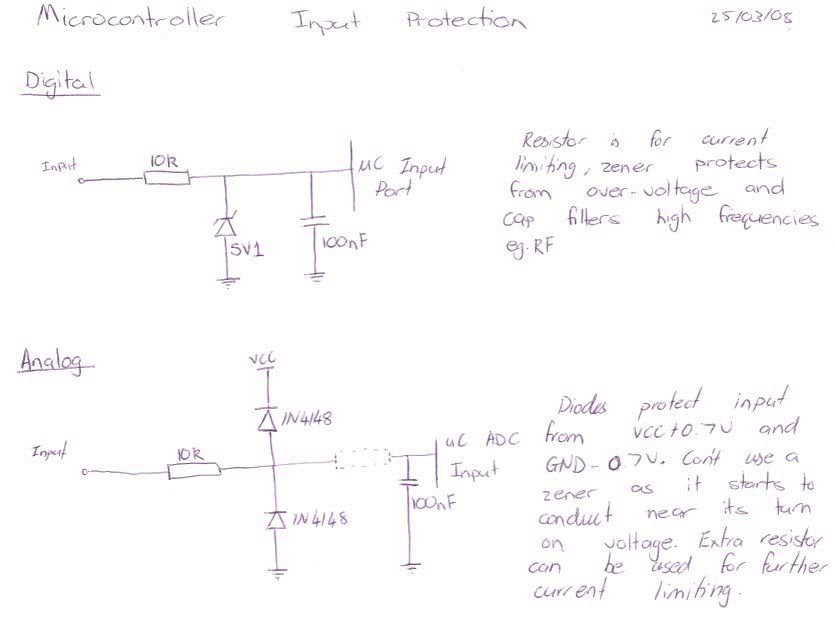
I figured out a few weeks back that Zeners have a conduction curve that starts significantly below their rated voltage, Cam saw that I was using them tonight and thought he'd put me straight.
I had thought of using a normal diode off the signal line to VCC also, but here it is in a nice diagram.
I have some additional points to add to that diagram :
For ADC inputs on our chip, they can't be used as outputs, and thus, the cap and resistor value are solely chosen based on RC filtering characteristics. This depends on which input it is and how much impedance it can drive and how fast and/or noise free we need that input to be.
For the digital inputs (except IRQ and XIRQ which are only inputs) the current limiting resistor must be chosen to limit current when the micro is set to output. this is around the 1.2 - 1.6k range or lower or higher depending on the requirements of drive to the particular device/from the particular input. Using 10R with the pin set to output could = dead chip.
Thanks for your input Cam you slack !@#$%*& :-p
Looking forward to your prototyping thread and associated corny pictures like Sean and I.
Admin.
DIYEFI.org - where Open Source means Open Source, and Free means Freedom
FreeEMS.org - the open source engine management system
FreeEMS dev diary and its comments thread and my turbo truck!
n00bs, do NOT PM or email tech questions! Use the forum!
The ever growing list of FreeEMS success stories!
FreeEMS.org - the open source engine management system
FreeEMS dev diary and its comments thread and my turbo truck!
n00bs, do NOT PM or email tech questions! Use the forum!
The ever growing list of FreeEMS success stories!
Re: FreeEMS hardware feature wishlist (your suggestions here!)
Many thanks to Carl Barnes from Tech Arts for allowing me to host this document :
http://www.diyefi.org/files/techart/AD9 ... 12sch1.pdf
It's the schematic for the adapt board which will be needed when designing any early FreeEMS main board.
Admin.
http://www.diyefi.org/files/techart/AD9 ... 12sch1.pdf
It's the schematic for the adapt board which will be needed when designing any early FreeEMS main board.
Admin.
DIYEFI.org - where Open Source means Open Source, and Free means Freedom
FreeEMS.org - the open source engine management system
FreeEMS dev diary and its comments thread and my turbo truck!
n00bs, do NOT PM or email tech questions! Use the forum!
The ever growing list of FreeEMS success stories!
FreeEMS.org - the open source engine management system
FreeEMS dev diary and its comments thread and my turbo truck!
n00bs, do NOT PM or email tech questions! Use the forum!
The ever growing list of FreeEMS success stories!

Re: freeEMS hardware feature wishlist (your suggestions here!)
I use these right now and they seem to be very rugged i have .080 traces for the supply to the coils and .080 for the ground input supply the the IGBT's (separate from the MCU ground plane) and they seem to work real good they dont even get warm with 4.0ms cranking dwell and 2.5 running on Suzuki C.O.P units they are To-220 package I was going to use D2Pak stly but they just took up so much room on the board i stuck with the through hole instead. The only draw back the this particular one is its a PBF style meaning you need to use mica insulators on them .Admin wrote:I propose that for ignition duties, sufficient places for to220 packages are put aside for on board drivers. If these are not desired, smaller self protected fets could be safely used to drive external peripherals larger fets for larger items with more current demand.
If the pin out of the chosen ign device does not match the common fet layout, a set of pads with jumpers could be included to re route the pins for the different part.
Having examined many options, the IRGB14C40L seems like a good choice. At high temperature it offers 14 amps continuous duty. Most coils require around 10 amps, thus the VB921 unit is not acceptable, and I was unable to find the remaining types for supply around the world.
Looking at the front of the unit, the pin order from left to right is 1 gate 2 drain 3 source for the IRGB14C40L
Having checked, the chosen FET pin layout turns out to be the same, so thats good. It will be best to provide space for as many heatsinked to220 devices as possible.
Admin.
The only draw back i can see to using the T0-220 is the need for all the screws for the heat sink bar i guess if you stacked them back to back you could cut the screw count in half and only use a screw on each end of the bus bar to the case, thats where the D2pak would be better so you would have to weight the options .
T0-220 takes less board space but more hardware.
D2pak takes more board space but no hardware.
One more thing to consider is the heat the D2pak style will transfer into the board seeing as it will use the board as a heat sink and if you have 24 FET's,mosfets,IGBT's all transferring heat into the board it might cause additional problems but i could be wrong .
Re: freeEMS hardware feature wishlist (your suggestions here!)
I was thinking the same thing. There is an option for that though : adhesive heat sinks for the top of each one. It could be an option :-)Tony wrote:One more thing to consider is the heat the D2pak style will transfer into the board seeing as it will use the board as a heat sink and if you have 24 FET's,mosfets,IGBT's all transferring heat into the board it might cause additional problems but i could be wrong .
I still think a through hole setup should remain an option for those that don't want SMD. Multiple designs can exist concurrently without issue, so this belief doesn't need to encroach on others that who don't like SMD.
Thank you very much for sharing your experiences with us.
Fred.
DIYEFI.org - where Open Source means Open Source, and Free means Freedom
FreeEMS.org - the open source engine management system
FreeEMS dev diary and its comments thread and my turbo truck!
n00bs, do NOT PM or email tech questions! Use the forum!
The ever growing list of FreeEMS success stories!
FreeEMS.org - the open source engine management system
FreeEMS dev diary and its comments thread and my turbo truck!
n00bs, do NOT PM or email tech questions! Use the forum!
The ever growing list of FreeEMS success stories!
Re: freeEMS hardware feature wishlist (your suggestions here!)
Yes your right leave it open to do what you want is the way to go, for a standard board stick with one or the other with a standard build sheet, and if you want to get adventurous change the design and try something new.Admin wrote:I was thinking the same thing. There is an option for that though : adhesive heat sinks for the top of each one. It could be an optionTony wrote:One more thing to consider is the heat the D2pak style will transfer into the board seeing as it will use the board as a heat sink and if you have 24 FET's,mosfets,IGBT's all transferring heat into the board it might cause additional problems but i could be wrong .
I still think a through hole setup should remain an option for those that don't want SMD. Multiple designs can exist concurrently without issue, so this belief doesn't need to encroach on others that who don't like SMD.
Thank you very much for sharing your experiences with us.
Fred.
Re: FreeEMS hardware feature wishlist (your suggestions here!)
I'm a fan of the long bar with all the componants perpendicular to the board, and the bar threaded between them. Easy on space, and you don't waster board real estate having them all bent over some bar.
Syncing that bar to the case is awesome, too.
Syncing that bar to the case is awesome, too.
-
thebigmacd
- LQFP112 - Up with the play
- Posts: 205
- Joined: Thu Apr 10, 2008 5:51 pm
Re: Letting go of the "MegaSquirt mindset" (hardware)
I work in HVAC controls (specifically with Delta Controls controls) and the super-duper do-everything board that they just discontinued used PC104 for network expansion cards. I really like the idea, but in reality the stack spacing ends up being quite large and with just one expansion card the thickness of the package is 1.5". Not so good.
I'm not sure on the viability of this idea I have, but why not set it up so the main board contains only logic level signals, then have a PCB-PCB edge connector at one end where interface hardware gets plugged in. Each interface card could have pass-through traces from one edge to another so multiple boards could be assembled end-to-end in a megasquirt-style extruded case. Just get a longer extrusion if you have more interfaces. Each interface board would then have associated I/O connectors on a third edge, which would be accessible through holes cut in the side of the case. This way functions could be segmented into separate connectors like automotive fuseboxes.
One could even go as far as defining standard PCB sizes like IT-style rack sizing (1U,2U,3U etc). A single injection IGBT driver could be on a 1U board, or use a 2U size and fit 4 on or something. Scalability and modularity.
And another alternative: define a rather large standard PCB, design a layout that can support all of the I/O one could ever imagine, but design it in such a way that each I/O channel has its own standard real estate on the board. If you want only two injector drivers, just populate two of the injector driver sections. Although the cost of the PCB in terms of physical size would be higher, there could be a lot of money saved on connectors over my first idea while still eliminating most of the jumper wires associated with MS.
Keith MacDonald
Control Engineering (Systems) Technologist
Control Engineering (Systems) Technologist
-
GartnerProspect
- LQFP112 - Up with the play
- Posts: 160
- Joined: Tue Apr 08, 2008 9:14 pm
Re: FreeEMS hardware feature wishlist (your suggestions here!)
I like the board edge idea but it would be hard to use because each board edge connector would take up 1/2" along the width of the board for every module. This would really crimp realestate without a really long extrusion. I haven't seen many instances where the size of the current MS case was a real limiting factor. That case easily has sufficient room for two boards if you don't have a bottom mounted MAP sensor so to me the idea of stacking works out better than going sideways.
Plus, by the time the logic levels made it to the last board it will have gone through a handful of connections, picking up noise all the way. Not sure if it's really an issue with 5+ signal. But I did like the side-mounted connector idea.
I think we can all agree on one thing for sure. All the wires needed with MS to connect the various upgrades is a hassle and messy. The PCB I'm designing right now will showcase my best efforts at meeting the challenges of extensibility. I think you'll like it I'll post up some specs and pics when I get closer to a presentable product.
Plus, by the time the logic levels made it to the last board it will have gone through a handful of connections, picking up noise all the way. Not sure if it's really an issue with 5+ signal. But I did like the side-mounted connector idea.
I think we can all agree on one thing for sure. All the wires needed with MS to connect the various upgrades is a hassle and messy. The PCB I'm designing right now will showcase my best efforts at meeting the challenges of extensibility. I think you'll like it