I think so. I might recommend planning for a larger regulator if possible. I believe yours are large enough, but this is also an area where it's easy to over build for little $ and little effort. Over building seems like cheap insurance to me. I believe you are saying that the switched 12V will power a pin on FreeEMS and then FreeEMS can choose to power down the larger regulator via a transistor switch. Is that correct? Seems reasonable to me.nitrousnrg wrote:Am I making sense?
Puma board for FreeEMS
Re: FreeEMS for Argentina
-
nitrousnrg

- LQFP144 - On Top Of The Game
- Posts: 468
- Joined: Tue Jun 24, 2008 5:31 pm
Re: FreeEMS for Argentina
Its reasonable. I bought LM2937 (500mA) and LM2940 (1A). I like the 2937 because it is really precise (is in charge of driving the analog circuits too)I might recommend planning for a larger regulator if possible. I believe yours are large enough, but this is also an area where it's easy to over build for little $ and little effort. Over building seems like cheap insurance to me
Current consumption is one thing to measure, I guess its near 200mA in that regulator.
I believe you are saying that the switched 12V will power a pin on FreeEMS and then FreeEMS can choose to power down the larger regulator via a transistor switch. Is that correct? Seems reasonable to me.

(I put the left side of R4 to 12v or gnd, allowing or not the current flow through the pnp)
It could drive the npn base directly from the switched 12v, or drive it from a cpu pin. Or both (the only minor issue of using both would be cpu protection)
I think the car key must power off all the extra circuits, so a hardware switch would be right. Also, it could help to prevent the initial pin polarity problems: if everything is powered down, cpu doesn't count, and polarity could be resolved with simple pullups/pulldowns instead of the xor gates. It would be right to switch everything on only when the cpu is ready (ie, not during a reset or bootload)
Ah, one more critical thing to measure: check the voltage drop between emitter and collector in the pnp.
.
Marcos
Re: FreeEMS for Argentina
I think I'm still a bit confused about your goal with that transistor switch. It looks like your giving FreeEMS the ability to switch off the 12V supply for things like the larger regulator, perhaps also the inj and ign?
Why use a Transistor instead of a MOSFET for the high side drive? Perhaps better yet, a relay. A transistor's e can cause some pain in the tuckas issues, and it would have to dissipate a fair bit of heat to keep saturated. A MOSFET could help decrease power consumed in the MCU case. However both would still have a leakage current when turned off. For low bandwidth / low cycle count, it's hard to beat the dissipated power and power capabilities of a dry contact.
Why use a Transistor instead of a MOSFET for the high side drive? Perhaps better yet, a relay. A transistor's e can cause some pain in the tuckas issues, and it would have to dissipate a fair bit of heat to keep saturated. A MOSFET could help decrease power consumed in the MCU case. However both would still have a leakage current when turned off. For low bandwidth / low cycle count, it's hard to beat the dissipated power and power capabilities of a dry contact.

Re: FreeEMS for Argentina
I've started a thread purely on the seperation of constant power and switched power subject :
http://www.diyefi.org/forum/viewtopic.php?f=9&t=903
Let's continue that general topic there and leave this one for Marcos' product :-)
Fred.
http://www.diyefi.org/forum/viewtopic.php?f=9&t=903
Let's continue that general topic there and leave this one for Marcos' product :-)
Fred.
DIYEFI.org - where Open Source means Open Source, and Free means Freedom
FreeEMS.org - the open source engine management system
FreeEMS dev diary and its comments thread and my turbo truck!
n00bs, do NOT PM or email tech questions! Use the forum!
The ever growing list of FreeEMS success stories!
FreeEMS.org - the open source engine management system
FreeEMS dev diary and its comments thread and my turbo truck!
n00bs, do NOT PM or email tech questions! Use the forum!
The ever growing list of FreeEMS success stories!
-
nitrousnrg
- LQFP144 - On Top Of The Game
- Posts: 468
- Joined: Tue Jun 24, 2008 5:31 pm
Re: FreeEMS for Argentina
nice, let's move it to another thread, after a little answer:
I've put the pnp just to make it easier to see how it works. A MOSFET should be there. A 10A solid state relay is around 20usd in digikey, I could overlooked that...
I've put the pnp just to make it easier to see how it works. A MOSFET should be there. A 10A solid state relay is around 20usd in digikey, I could overlooked that...
Marcos
-
nitrousnrg
- LQFP144 - On Top Of The Game
- Posts: 468
- Joined: Tue Jun 24, 2008 5:31 pm
Re: FreeEMS for Argentina
So far, this is what I'm implementing.

Vref is just the regulator output... not a proper reference.
EDIT: nicer drawing

Vref is just the regulator output... not a proper reference.
EDIT: nicer drawing
Last edited by nitrousnrg on Sun Oct 10, 2010 4:21 pm, edited 1 time in total.
Marcos
Re: FreeEMS for Argentina
leccion ingles: "i could overlook that" or "i could have overlooked that" but not what you have :-) which is it?
Which reminds me, I have a lot of catching up to do on my Espanyol study! :-(
Which reminds me, I have a lot of catching up to do on my Espanyol study! :-(
DIYEFI.org - where Open Source means Open Source, and Free means Freedom
FreeEMS.org - the open source engine management system
FreeEMS dev diary and its comments thread and my turbo truck!
n00bs, do NOT PM or email tech questions! Use the forum!
The ever growing list of FreeEMS success stories!
FreeEMS.org - the open source engine management system
FreeEMS dev diary and its comments thread and my turbo truck!
n00bs, do NOT PM or email tech questions! Use the forum!
The ever growing list of FreeEMS success stories!
Re: FreeEMS for Argentina
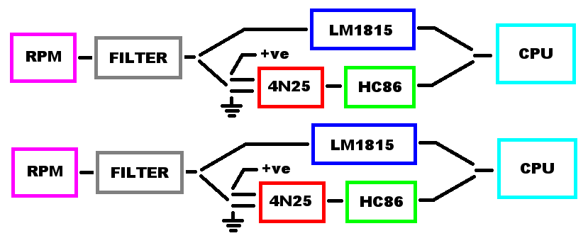
RPM input prelim circuit from ages ago, which reminds me, do you plan to support logic level inputs as well as VR? If so, you need to condition them somehow anyway. This shows that at the time I drew it, I didn't think inversion was required for VR stuff, but it was required for non vr stuff.
http://i260.photobucket.com/albums/ii15 ... ration.png
PS, what is "EN" ?
PPS, do you mean "motor drivers, ign drivers, injection drivers" and "motor ign injection" in those two boxes in your diagram?
Fred.
http://i260.photobucket.com/albums/ii15 ... ration.png
PS, what is "EN" ?
PPS, do you mean "motor drivers, ign drivers, injection drivers" and "motor ign injection" in those two boxes in your diagram?
Fred.
DIYEFI.org - where Open Source means Open Source, and Free means Freedom
FreeEMS.org - the open source engine management system
FreeEMS dev diary and its comments thread and my turbo truck!
n00bs, do NOT PM or email tech questions! Use the forum!
The ever growing list of FreeEMS success stories!
FreeEMS.org - the open source engine management system
FreeEMS dev diary and its comments thread and my turbo truck!
n00bs, do NOT PM or email tech questions! Use the forum!
The ever growing list of FreeEMS success stories!
-
nitrousnrg
- LQFP144 - On Top Of The Game
- Posts: 468
- Joined: Tue Jun 24, 2008 5:31 pm
Re: FreeEMS for Argentina
"i could have overlooked that" heheleccion ingles: "i could overlook that" or "i could have overlooked that" but not what you have :-) which is it?
I saw your spanish git repo this week, and almost mail you, just to complete some of the unknown words.
Do you know if a LM1815 or MAX9926 can handle digital inputs? VR signals are much more tough than 0-5v, or 0-12v square signals. I was wondering if I can use the same circuit to interface VR or Halls.RPM input prelim circuit from ages ago, which reminds me, do you plan to support logic level inputs as well as VR? If so, you need to condition them somehow anyway. This shows that at the time I drew it, I didn't think inversion was required for VR stuff, but it was required for non vr stuff.
What is the difference between VR and non VR, regarding inversion?
EN = enablePS, what is "EN" ?
PPS, do you mean "motor drivers, ign drivers, injection drivers" and "motor ign injection" in those two boxes in your diagram?
and wow, I've to edit that image... is too confusing. Yep, 5v are associated with drivers, 12v with driven actuators.
I checked kicad's footprints against my new, shiny components. So far I can tell my printer is not even close to a 1:1 scale ¬¬
Marcos
Re: FreeEMS for Argentina
LM1815 definitely can't handle a square wave. I don't know about the other. It's 5am, too tired to think about inversion stuff right now. :-)
DIYEFI.org - where Open Source means Open Source, and Free means Freedom
FreeEMS.org - the open source engine management system
FreeEMS dev diary and its comments thread and my turbo truck!
n00bs, do NOT PM or email tech questions! Use the forum!
The ever growing list of FreeEMS success stories!
FreeEMS.org - the open source engine management system
FreeEMS dev diary and its comments thread and my turbo truck!
n00bs, do NOT PM or email tech questions! Use the forum!
The ever growing list of FreeEMS success stories!